Additive Manufacturing
Although additive manufacturing is a relatively young discipline, the effects that can be achieved with the various additive technologies in terms of efficient product and manufacturing process optimisation are of outstanding importance. These processes offer innovative and versatile possibilities for accelerated product design as well as extended optimisation of the design and manufacturing processes. In addition, by utilising technologies based on nature, it is also possible to manufacture components with extreme complexity and internal structures, which is very difficult or even impossible with conventional processes.
 ©
IPeG
Construction and simulation
The following tools are used at the institute for design and simulation in additive manufacturing:
- Autodesk Inventor
- Autodesk Netfabb Ultimate
- Autodesk Netfabb Local Simulation
- Abaqus
- Ansys
Additive Learning factory
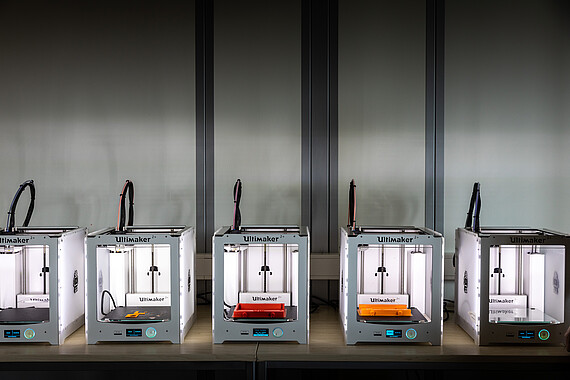
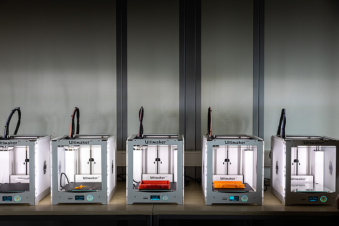
- Machines:
- 1 x Ultimaker S5
- 1 x Ultimaker S3
- 12 x Ultimaker S2+
- Material: PLA, ABS, Nylon, PC, TPU, PP
- Support material: PVA (water-soluble)
- Process: Fused layer modelling
- Installation space: > 285 x 153 x 155
- Resolution z: 0.1 mm
- Application examples: Student work, rapid prototyping
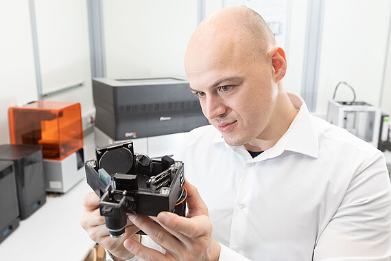
Optics production
- Machine: Objet30 Pro
- Material: FullCure (853, 840, 870, 850 and 810), Transparent (VeroClear) and High Temp (RGD5245)
- Support material: FullCure 705 Support
- Process: PolyJet
- Installation space: 300 x 200 x 150 mm
- Resolution z: 16 µm or 28 µm depending on material
- Application examples: Precision components, optical elements
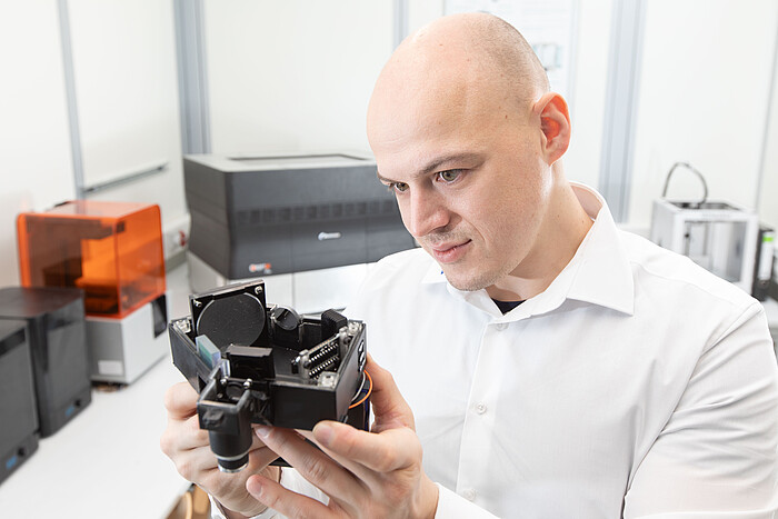
- Machine: Formlabs form 2
- Material: Synthetic resin materials
- Process: Stereolithography
- Installation space: 145 x 145 x 175 mm
- Layer thickness: 25 - 300 μm
- Application examples: Precision components, optical elements
- Machine: Formlabs form 3
- Material: Synthetic resin materials
- Process: Stereolithography
- Installation space: 145 x 145 x 185 mm
- xy resolution: 25 µm
- Layer thickness: 25 - 300 μm
- Application examples: Precision components, optical elements
 ©
IPeG
Plastic Laser Sintern
- Machine: EOS Formiga P110
- Material: PA2200 (polyamide), others possible
- Process: Selective laser sintering
- Installation space: 200 x 250 x 330 mm
- Resolution: 60 µm - 120 µm
- Application examples: Precision components, structural components, functional prototypes


 ©
IPeG
Metal Laser Sintern
- Machine: EOSINT M280
- Material: X3NiCoMoTi 18-9-5 (hot-work tool steel), AlSi10Mg (aluminium), others possible
- Process: Laser Powder Bed Fusion
- Installation space: 250 x 250 x 325 mm
- Resolution: 30 µm - 50 µm
- Application examples: Structural components, optical elements, heat sinks, precision components
Multi-Material - Metal Laser Sintern
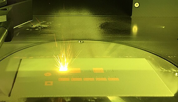
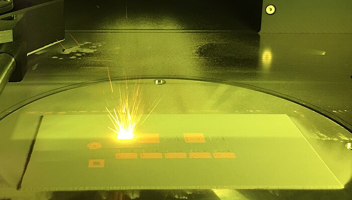
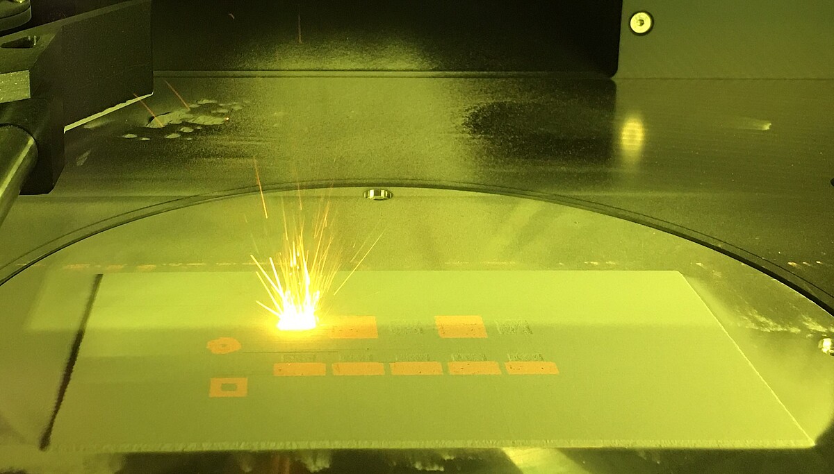
- Machine: Aconity MIDI+
- Material combinations: CuCrZr - 316L, AlSi10Mg - 1.2709, others possible
- Process: Laser Powder Bed Fusion
- Installation space: 100 x 230 x 250 mm
- Lateral powder pixel resolution: 500 µm
- Resolution: 30 µm - 50 µm
- Application examples: Heat exchangers, electric motors, heat sinks
Large-scale production system for scale-independent additive manufacturing and repair
- Machine: Aconity MIDI+ 2.5 m Extended
- Manufacturing scenarios:
- Additive manufacturing of components up to 2.5 m in size
- Hybrid manufacturing:
- Additive repair & refurbishment
- Functionalisation of existing components
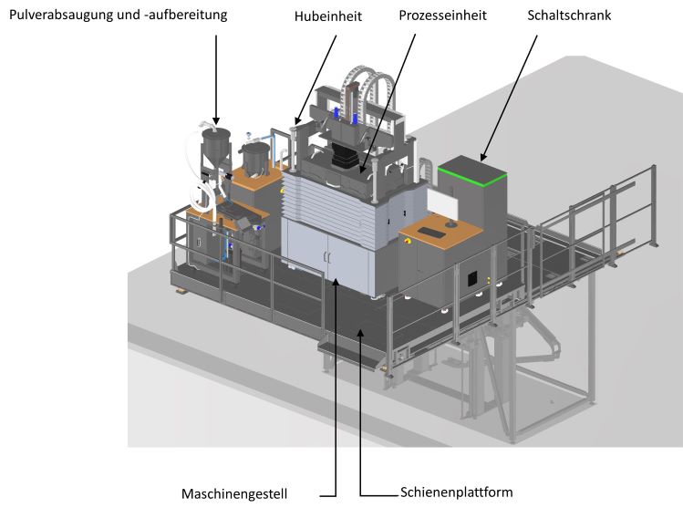
- System concept: The additive manufacturing centre consists of three basic components:
- Rail system
- Lifting system
- PBF-LB/M system
- Dimensions:
- Maximum component length: Up to 2500 mm
- Maximum component diameter: Up to 250 mm
- Materials used:
- Monomaterials: Aluminium, copper and steel alloys
- Multi-material: Extension to copper / steel or copper / aluminium possible
- Process: powder bed fusion of metals using a laser beam (PBF-LB/M)
Post-processing
For the post-processing of additively manufactured components, IPeG also has equipment for flow grinding (AFM ECOFLOW 100) and vibratory grinding (Multivibrator "AM-1") in addition to machining production processes. These manufacturing processes enable complicated free-form geometries and internal channels to be reworked effortlessly.
Quality assurance
Process monitoring
- Camera for inline process visualisation
- Process monitoring: High-speed CMOS camera
- Single pyrometry: Measurement of thermal radiation of the melt pool
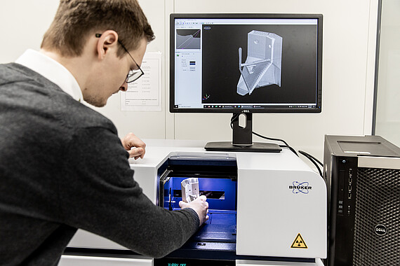
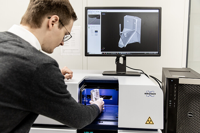
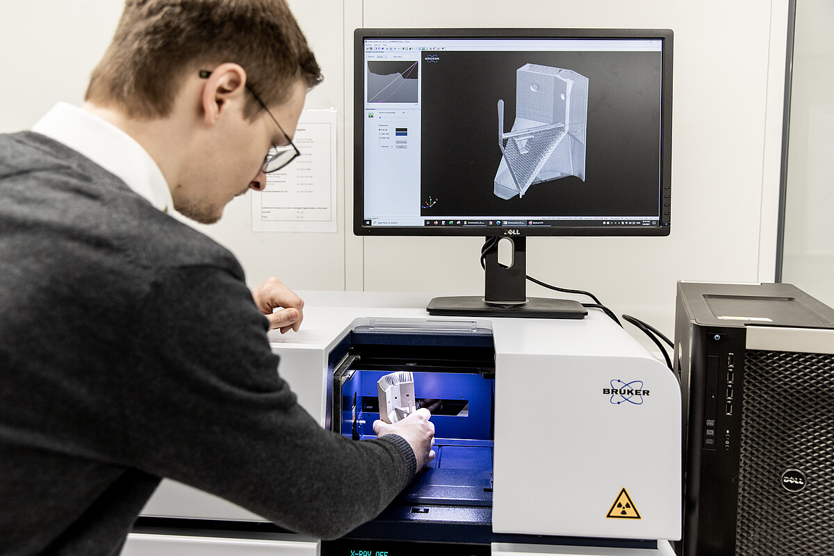
Micro-computed-Tomograph
- Machine: Bruker microCT, model SkyScan 1275
- X-ray energy: flexible up to 100 kV
- Resolution: 4 μm/px to 50 μm/px
- Max. Sample size: Ø96mm, H120mm
- Scan mode: Fully automatic
- Fastest scan: 80 sec
- Functions: Calculate porosity, detect inclusions, calculate volume, assess dimensional and shape deviations, create STL geometries
 ©
IPeG
Surface measurement fringe projection
- Machine: Zeiss COMET L3D 5M
- Resolution: 2448 x 2050 px
- Measuring volume
- 100 measuring field: 120 x 100 x 60 mm
- 500 measuring field: 480 x 400 x 250 mm
- 3D point spacing
- 100 measuring field: 50 µm
- 500 measuring field: 190 µm
- Scan mode: Fully automatic
- Processing software: Colin3D Functions
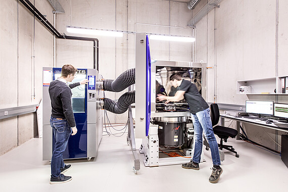
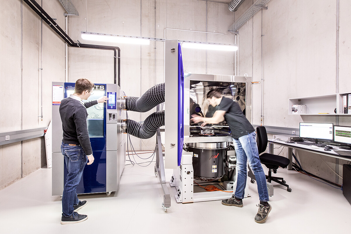
Multi-physics test bench
- Machine: IMV Corporation, Model A22/EM2HAM
- Application: Thermomechanical loading
- Sinusoidal excitation:
- F_max = 22 kN
- a_max = 956 m/s²
- Frequency range: 5 < f < 3300 Hz
- Temperature range: -60°C to 170°C
- Mass of test object: mmax = 300 kg
- Functions
- Modal analysis
- Damping
- Natural frequency
- Natural modes
- Lifetime analysis
- Property validation

 ©
IPeG


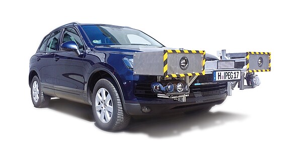
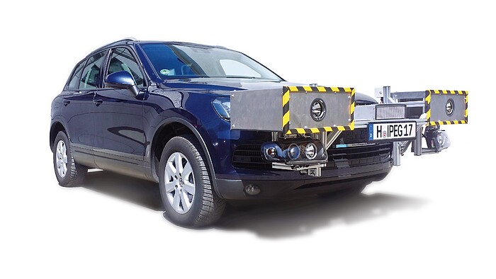
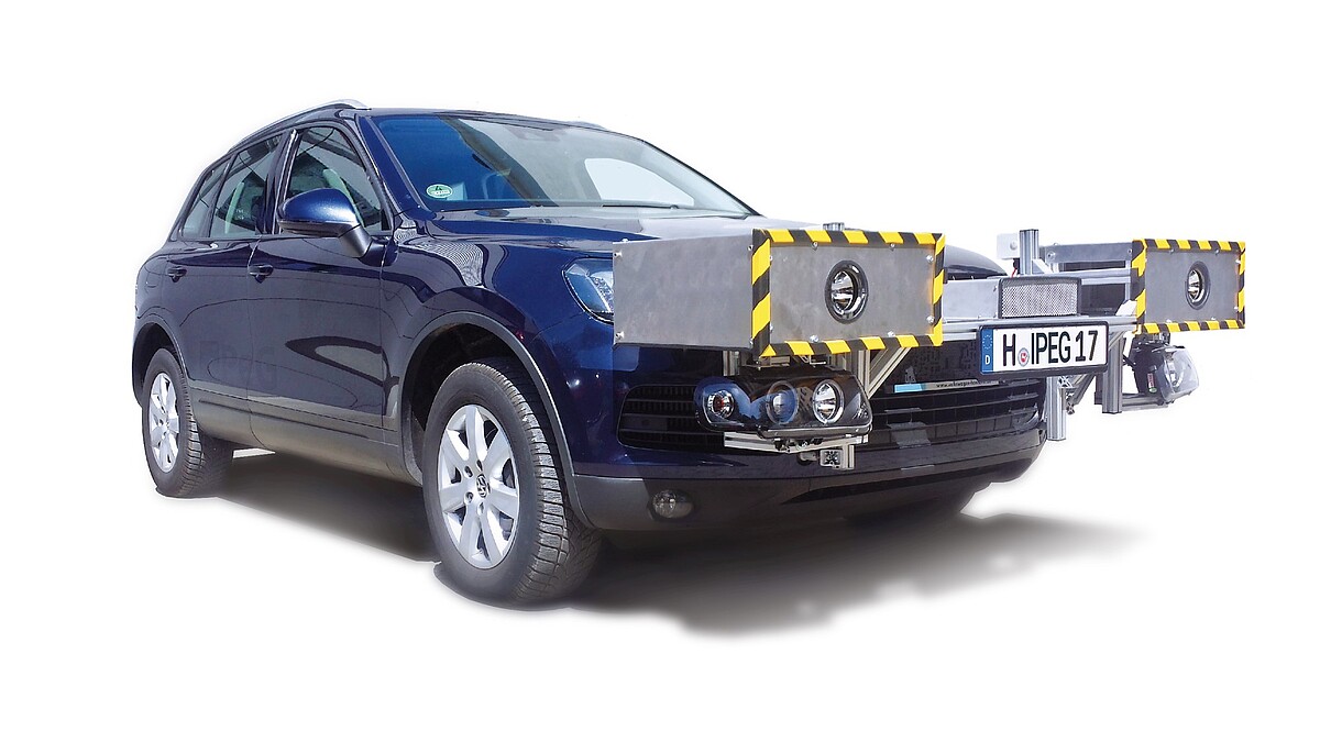
Light test vehicle
Road-legal test vehicle for the investigation and metrological validation of headlight prototypes developed at our institute. The vehicle is also equipped with a camera system and a processing unit for recording and processing the measurement data and monitoring the traffic area.
 ©
IPeG
Light measurement technology
Our equipment includes various measuring devices for the photometric validation of light sources and lighting systems.
With our integrating spheres in sizes from 20 cm to 2 m and associated spectrometers as well as a double monochromator, we carry out spectral measurements from 300 to 1000 nm, measure colour coordinates (colour coordinates) and colour temperature and determine the efficiency of the light source or luminaire.
We also have a near-field goniophotometer with a luminance camera for measuring the light distribution, luminous intensity and luminance of light sources or luminaires. It can also be used to determine luminous flux and colour location.
Simulated light distributions can be generated from the measurement data on a screen at any distance. These measurements are also possible with our far-field goniophotometer, which with its photometer heads fulfils the highest accuracy class L according to DIN 5032/7 and is ideal for measuring headlights and signal lights.
We would be happy to provide you with a customised quotation for measuring your lamp or luminaire.


